Crossing the chasm in everyday wearable XR eyewear
Dispelix develops and delivers transparent waveguides that are used as see-through displays in extended reality (XR) devices. Our optical combiner technology is well-suited to a wide range of form factors, from near-eye to head-up displays.
SUMMARY OF INSIGHTS
- User experience of XR eyewear is impacted by three XR comfort dimensions: social, wearable and visual comfort.
- Dispelix’s unique design capability stretches from near-eye displays for smart glasses, headsets, and helmet-mounted devices to head-up displays.
- Dispelix’s waveguide display technology is broadly compatible with LED and laser light engines.
- Dispelix designs are created, simulated, and toleranced for manufacturing using the powerful and versatile Dispelix Waveguide Studio™ software tool.
- Dispelix manufacturing concept is robust, scalable and validated for volume manufacturing, and compatible with standard semiconductor processes and equipment.
- Dispelix is a fabless company that works in close collaboration with the world’s leading display and semiconductor manufacturers.
- Dispelix is part of a strong, vibrant ecosystem that fosters innovation in and commercialization of XR.
The Dispelix design vision
User comfort
As an eyewear product, XR glasses instantly become more than technology as soon as the user puts them on. They are part of the user’s presence and identity; they have a unique look and feel. While it brings undeniable technological benefits compared to alternatives like smartphones, XR technology must also address these often-unconscious user expectations. This is why XR technology cannot be designed and evaluated purely on technical grounds; rather, a more human-centric approach is needed. At Dispelix, our ultimate design vision is to create technology that does not look like technology. We want to enable XR glasses that look, wear, and feel like ordinary glasses. That’s why our design principles are fundamentally built on three dimensions of comfort: social, wearable, and visual. 1 These three dimensions of comfort in the context of XR are explained in more detail below.
- Social comfort: At the heart of social comfort are esthetics, the ability to connect and communicate with surroundings in a natural way, and privacy. Unique and appealing esthetics create emotional value for a consumer, building affection towards the product and supporting acceptance by others. The user must be able to interact in social settings in a natural way and maintain eye contact. In addition, other people in the setting must be able to see the user’s eyes. The essential function of an XR display is to deliver augmented content to the user. This content must always stay private to the user.
- Wearable comfort: XR glasses may be worn for extended periods of time, depending on the user’s needs and preferences. This means they must be lightweight, with a balanced center of gravity. As with regular eyeglasses, there must be sufficient distance between the eye and the lens or display. XR glasses must also be able to provide the same sense of safety as regular glasses. This translates into a see-through display and unconstrained peripheral vision to allow awareness of surroundings.
- Visual comfort: XR glasses must provide visual comfort and consumer-grade image quality approaching that of smartphone displays. The experience of viewing the virtual content must be as natural as possible without any visual strain. The image brightness must be adequate and adjustable for varying ambient light conditions, understanding that the brightness required on a sunny day is substantially more than the brightness needed in typical indoor lighting conditions. Image quality – most importantly sharpness, color gamut, and uniformity – must be such that it enables a pleasant visual experience while accurately relaying detail without any visible artefacts. The field of view must be wide enough to leave some freedom for the user to choose the ideal location of the XR content while at the same time accounting for the limitations of the human field of view.
Dispelix technology
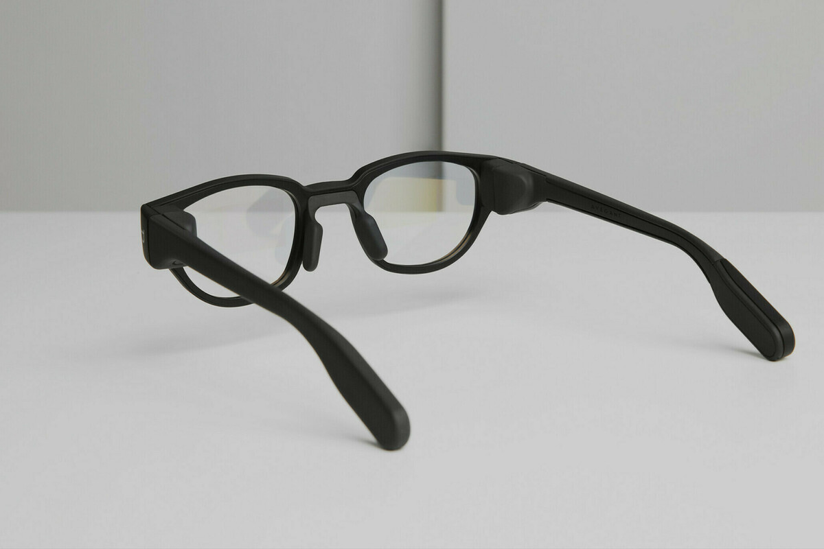
Our full-color, near-eye displays encompass all three of the dimensions of XR comfort – social, wearable, and visual – in a simple eyeglass form. They provide a powerful platform for optical see-through implementation that paves the way for broader adoption of XR eyewear.
Social comfort
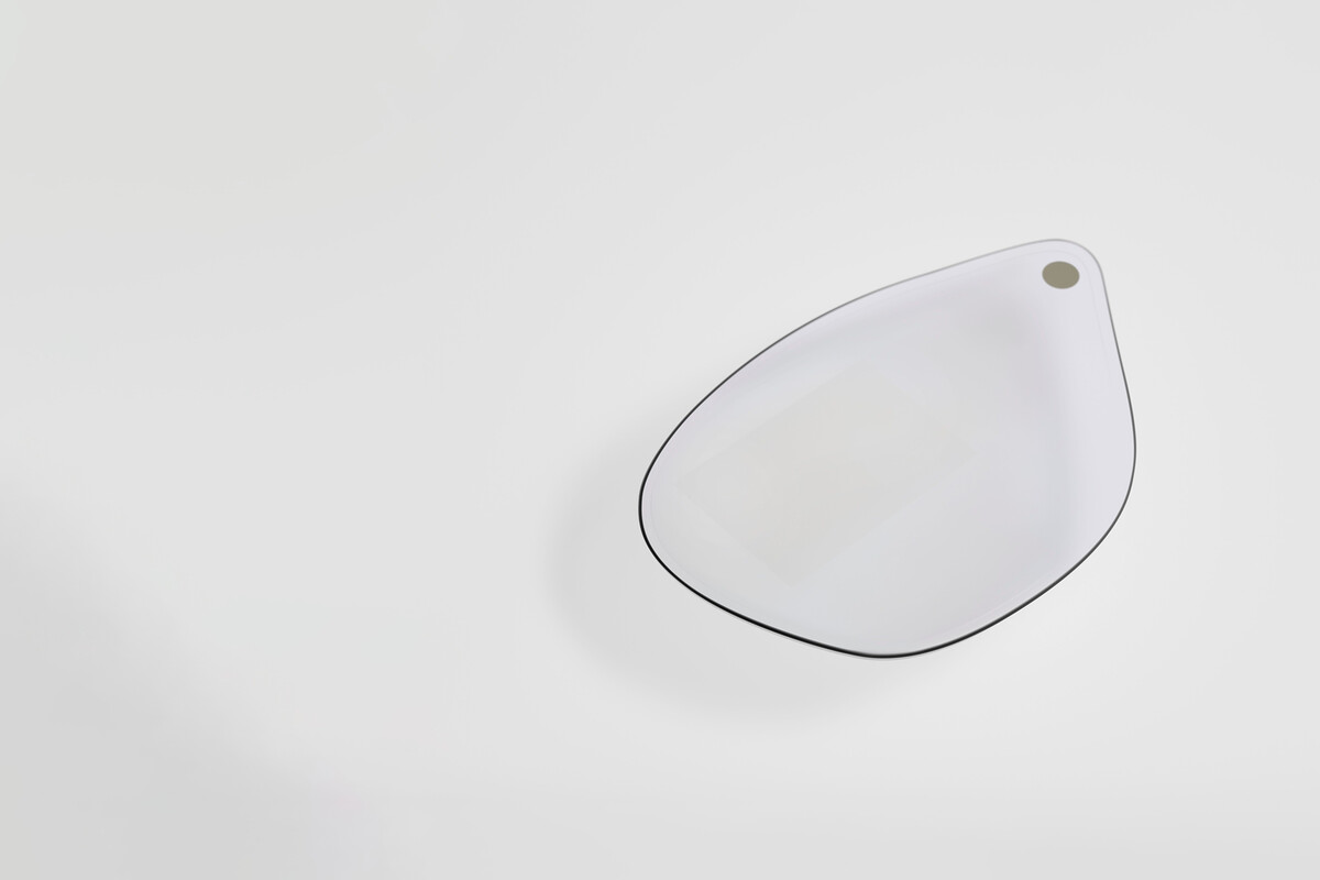
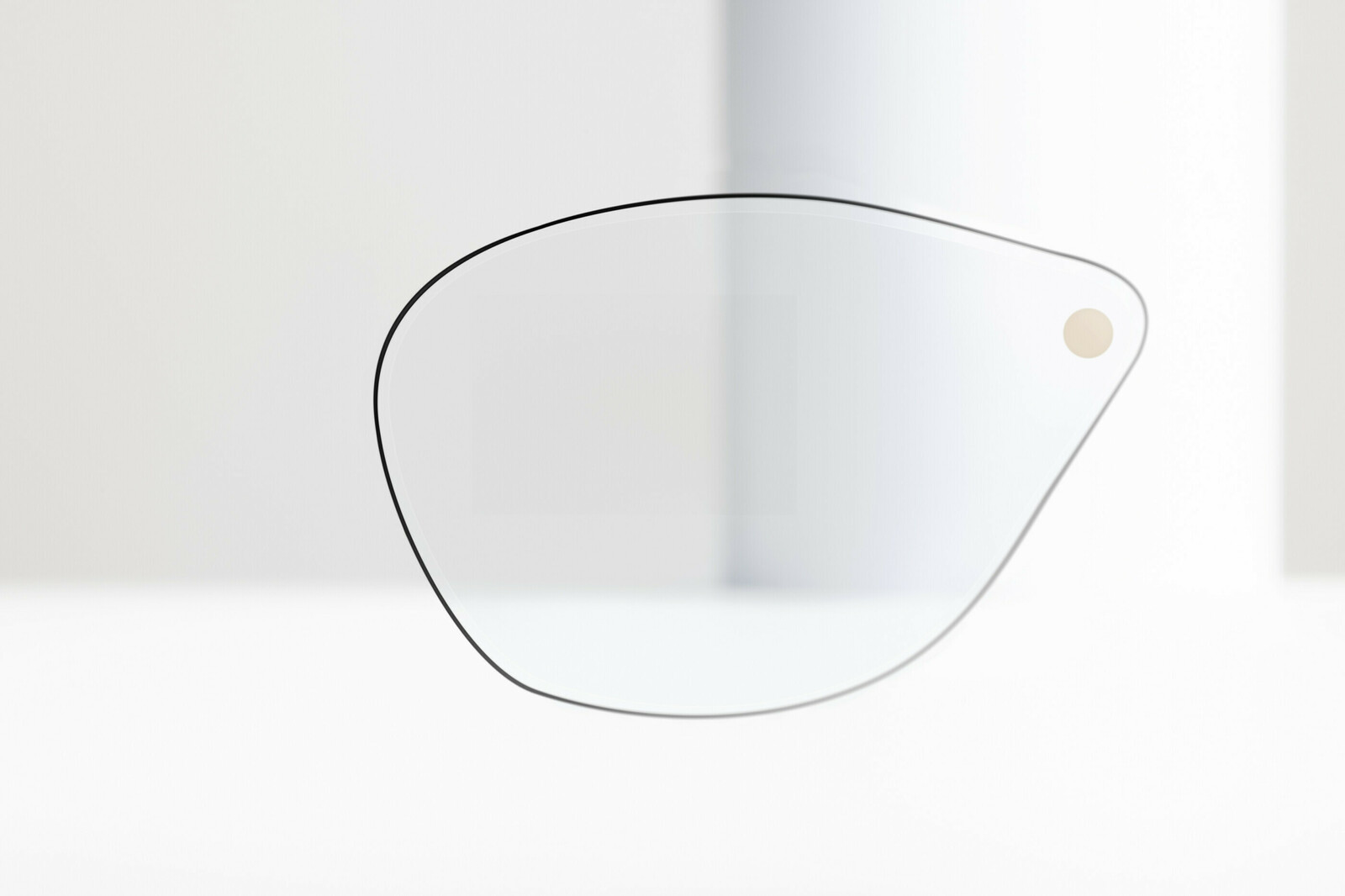
XR esthetics is created by designing in eyeglass form. Dispelix XR combiners enable an eyeglass form, with a waveguide combiner shape that imitates lens and frame angles fitted to a facial curvature. Diffractive elements are optimized to fit into lens-like shapes. A natural, thin side-profile is created through single-layer design and by adding a pantoscopic tilt like that of regular eyeglasses.
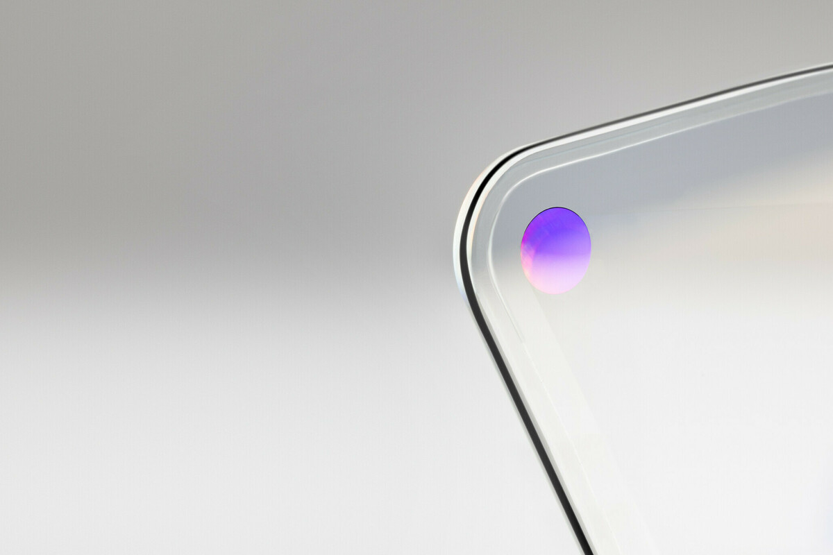
Transparency is ensured in Dispelix designs through material selections and grating design. In Dispelix designs, the grating reflection spectrum is matched with that of the substrate. Gratings are designed to be discreet and nearly invisible. To support this, ambient light reflections from diffractive elements are minimized for all angles. The glass substrate and associated layer structure is selected to provide high transparency across the entire visible spectrum, including the challenging blue end of the spectrum.
Elimination of world-side leakage of luminance serves a two-fold purpose: First, it cuts down the awkward glow effect often visible in XR devices when they are switched on. Second, it keeps the content private for the user. Dispelix waveguide combiners are designed to minimize this undesired world-side leakage.
Wearable comfort
Weight is minimized by optimizing the footprint of the diffractive elements. Dispelix’s thin, single-layer design not only creates elegant esthetics but also contributes favorably to the lightweight feel of XR glasses.
We balance the design by adjusting the pantoscopic tilt and frame wrap to match that of traditional eyeglasses. Top-corner coupling from the temple side helps to adjust the center of gravity towards the head side, thus preventing the uncomfortable feeling of the glasses sliding along the nose bridge.
Eye relief has been designed to maintain a comfortable distance from the waveguide combiner and to leave sufficient room for prescription integration. We optimize the distance to ensure that the eye relief does not become large to cause the device’s center of gravity to shift too far from the user’s head.
Peripheral vision allows the user to see to the side without moving their head. In contrast to central vision, peripheral vision is not accurate; it merely allows the user to detect color, shape, and movement. The sharp foveal vision only covers a narrow 3 degrees. Text recognition is possible up to 20 degrees in the horizontal field of view. Shape and color recognition extend to 40 degrees and 60 degrees respectively. Peripheral vision is critical to alertness and safety; thus, it is important that the design does not obstruct it. Dispelix see-through displays allow unrestricted peripheral view in the same way as eyeglass lenses.
Visual comfort
The eyebox is the three-dimensional space between the eye and the display through which the full field of view is visible to the user. A larger eyebox allows a natural, unconstrained field of view that does not place strain on the eyes, making a critical contribution to visual comfort. A large eyebox provides design flexibility to adjust interpupillary distance to match wider user segments. The downside of a large eyebox is that it spreads the available luminous power across a larger area, thus decreasing overall brightness. In addition, the eyebox is inversely proportional to the field of view – the larger the field of view, the smaller the eyebox and vice versa. Creating the optimal eyebox size requires careful analysis of the pros and cons of different aspects of visual comfort and performance during the design phase.
Field of view is the angular segment of the human field of view into which XR content can be brought and seen by the user with unconstrained eye movement. The field of view of our standard product accounts for the limitations of human vision and offers a carefully tailored balance between image sharpness, uniformity, and brightness in a compact eyeglass form. The optimal XR field of view is use case specific, Dispelix’s design capability enables extremely high diagonal field of view. The field of view is also impacted by light engine properties and set-up, including incoming luminous power, aspect ratio, image resolution, and refresh rate.
The display brightness, or in more scientific terms the luminance, depends on the luminous power of the light source and the waveguide combiner’s ability to pass this power from the in-coupler all the way to the eyebox with low loss. The ability to retain brightness is known as brightness efficiency, and for Dispelix waveguide combiners it has been optimized through efficient interface design between the light engine and in-coupler and sophisticated diffractive element design throughout the waveguide combiner. The brightness provided by Dispelix waveguide combiners and commercially available light engines is high enough for both indoor and outdoor use.
Sharpness is another human-perceived quality that is related to quantifiable metrics through contrast and resolution. Modulation transfer function (MTF), on the other hand, is the key metric that links contrast to spatial resolution. It is widely used to assess the image sharpness of optical systems. MTF defines the human-perceived image quality and, more broadly, the user experience offered by an XR display to a large extent.
Dispelix’s surface relief grating based XR waveguide combiners are designed to enable the creation of virtual displays with high image sharpness. Diffractive waveguides lack the geometric distortions that are typical for the aspherical lenses traditionally used in imaging optics. This is because light propagation and diffraction from flat surfaces and periodic structures is a highly deterministic process that can be simulated accurately. The sharpness degradation in surface relief grating-based waveguide combiners typically results from manufacturing imperfections and from inaccuracies in substrate flatness. Dispelix’s technology choices – direct etch, high-refractive index planar glass substrates, and single-layer design for all color bands – mean that both these sources of imperfection have been minimized to such an extent that they are almost negligible.
The Dispelix advantage
Dispelix XR technology is created in Waveguide Studio, our powerful, proprietary optical waveguide design tool that uses advanced algorithms, AI, and modern computing strategies. It allows creative design ideas with fast simulation capacity to find optimum performance and tolerancing. Our core technology supports versatile form factors, architectures, and material combinations. Our design capability covers everything from thin, minimalistic eyeglass forms to tailored headsets and head-mounted devices all the way to mounted or integrated head-up displays. Dispelix’s purposely simple and robust manufacturing concept is widely applicable to different diffractive waveguide combiner form factors and architectures.
Design
Any commercially viable XR concept must meet the demanding image quality expectations set by today’s advanced smartphone displays. At the same time, XR designs must deliver social, wearable, and visual comfort for users. This translates into a need for compact waveguide combiner designs with uncompromised performance and image quality. The design of diffractive optical systems is extremely intensive in terms of the required computing power. Together, these factors set demanding requirements for waveguide combiner design and for the software tools used in the process.
To be successful in the fiercely competitive field of XR, one must master waveguide design. To do this, Dispelix has invested heavily in algorithm development and in-house design capability. Dispelix’s in-house design tool provides a rigorous physical model of a diffractive optical waveguide system. The simulation tool also considers the phase of the light and therefore includes interference effects occurring in the waveguide. The tool can solve complex, multi-objective optimization problems quickly and efficiently. A human-centric vision model and manufacturing tolerancing are also incorporated in the Dispelix tool. The tool is compatible with high-performance computing clusters, thus scaling up the available computing power significantly.
Scalable manufacturing concept
The Dispelix manufacturing concept is purposely maintained simple and compatible with standard semiconductor processes and equipment. It has been systemically validated for mass production. We collaborate closely with our ecosystem network to scale-up volume production, establishing processes and metrology for safe mass-production ramp-up. Our professional team takes care of management for the whole product lifecycle, from concepting and verification all the way to delivery, with quality and supply assured at every step.
We have laid the foundations for a manufacturing concept based on three critical pillars:
- Only inorganic materials are used in Dispelix waveguide combiners. Inorganic materials are necessary to achieve the high optical performance we demand from our components. Inorganic substrates and coatings together ensure consistent quality and resistance to environmental factors like fluctuations in humidity and temperature. This contributes tremendously to long-term component reliability, a characteristic that Dispelix sees critical in both consumer and enterprise applications.
- Direct plasma etching is used to fabricate the surface-relief grating structures into the waveguide. This ensures high pattern fidelity and allows fabrication of complex grating shapes. As a result, we gain extensive design freedom to optimize grating response for the selected architecture and customer requirements. Direct etching does not limit lithography options; it is compatible with both contactless and nano-imprint lithography methods.
- Accurate, repeatable, and reproducible metrology is critical for any successful technology scale-up. Commercial-level XR is a newcomer among display technologies. Due to its virtual nature, it is uniquely different from traditional displays, with no broadly accepted industry standard to rely on. This is why Dispelix actively develops new measurement concepts and methods for XR image quality and inline process control. We work with leading measurement system and equipment manufacturers to ensure meaningful XR metrology is used in the manufacturing of Dispelix SRG technology. We have implemented metrology to systematically cover the complete component lifecycle from design verification to mass manufacturing quality control.
A manufacturing concept that is both simple and robust allows us to maintain consistent quality while at the same time delivering excellent optical performance in the form factor the customer desires, whether it be an elegant eyeglass-form near-eye display or a head-up display capable of performing reliably in demanding conditions. Our fully validated manufacturing concept provides a proven path for the safe scale-up of new combiner designs and design generations.
Creative power
The Dispelix approach, our unique design expertise, and our manufacturing concept together enable waveguide combiners with enterprise-grade image quality, exceptional sharpness and detail, and optimized image uniformity with full and vibrant colors. Our waveguide combiners can be used for both monocular and binocular use. Our human-centric design approach, which prioritizes the factors that contribute to high human-perceived image quality, sets the foundation of our design principles. Dispelix has extensive abilities to customize and tailor designs to create desired form factors and optical performance for near-eye and head-up displays.
Ecosystem
At Dispelix we firmly believe that success is achieved together. Dispelix is part of a wider ecosystem that fosters innovation in and commercialization of XR technology. This network includes OEMs, ODMs, projector and sensor technology providers, material suppliers, and component manufacturers. Dispelix has joined forces with leading manufacturing powerhouses to scale up volume production of its diffractive waveguide combiner designs. We work in close collaboration with leading material suppliers, metrology equipment manufacturers, and foundries to deliver waveguide combiners with consistent quality for our customers.
Integration
Dispelix waveguide combiners are integrated into an XR device frame with light engine and other technology elements, typically including at least a battery, chips for wireless connectivity, and sensors for boosting performance and adding features. All these elements must function seamlessly together. Dispelix waveguide combiners are designed to maximize comfort and optical performance in combination with a light engine. This brings a myriad of interface aspects, especially for the light engine. Mechanical integration, beam characteristics, and the light source luminous spectrum are specified to deliver the best possible performance while allowing for cost-effective integration.
Light engines
An XR optical display module comprises a miniaturized light engine and a waveguide combiner. The characteristics of both the waveguide combiner and light engine contribute significantly to the overall XR experience through all three dimensions of comfort: social, wearable, and visual. Ideally, the light engine and display are designed for each other. We at Dispelix recognize this need and work closely with our light engine partners for maximum compatibility. Dispelix waveguide combiners are agnostic to the underlying light-engine approach. They can be integrated with all major LED-based light engines including LCoS, DLP, and microLED. Dispelix has a separate waveguide combiner for coherent and narrow-band laser irradiation.
Let's define the future of extended reality together
Dispelix’s optical see-through waveguide combiners open new avenues in the realm of XR displays. Our unparalleled design expertise ranges from lightweight, wearable near-eye displays all the way to integrated head-up displays for premium transportation vehicles. Dispelix’s manufacturing concept is purposely robust, simple, and compatible with standard semiconductor processes and equipment. These conscious decisions ensure safe scale-up, consistent quality, and long-term reliability of our components. We are part of a vibrant ecosystem that helps you to realize your most bold product visions from waveguide display design all the way to finalized, mind-altering XR experience.
Glossary
Coherence describes how well lightwaves are synchronized with each other. Coherence has two aspects, spatial and temporal. Spatially coherent lightwaves move in unison and have strong correlation on the transverse plane, or across the beam profile. They are at the same phase across the transverse plane in reference to the direction of beam propagation. Temporally coherent lightwaves, on the other hand, share the same frequency along the direction of propagation; the correlation between time and distance traveled is strong.
Color gamut is the range of colors, or tones, that can be reproduced by the optical system. International Commission of Illumination (CIE) chromaticity maps are useful in presenting the complete color gamut and the subset of the color gamut achievable by the optical system.
Contrast in a display context refers to how well black and white can be distinguished when they coexist in an image. There are several ways to define and measure display contrast, with the most common methods being ANSI checkerboard contrast and FOFO (full-on/full-off) contrast.
Eyebox is the volume between the eye and the XR display within which unconstrained, natural pupil movement is allowed, yet full field of view is visible to the user.
Eye relief refers to the distance between the outer surface of the cornea and the waveguide combiner at a distance where the user can still comfortably see the full field of view.
Field of view (FOV) refers to the angular segment or range of the observable world visible to the human eye or any other device with a lens system (camera, microscope, binocular, telescope, etc.). FOV has both horizontal and vertical extends and can be defined for monocular or binocular vision.
Frame-wrap refers to the angle waveguide combiners make from the frontal plane, towards the temple sides.
Light engine provides the image source for an optical display module. Light engines can be self-emissive (microLED, OLED) or reflective (LCoS, DLP). Light engine entails light sources and miniaturized projection optics. In the case of reflective light engines, illumination optics are also needed. Laser-based light engines utilize MEMS-mirrors to perform algorithm-driven laser beam scanning operation.
Luminous power, also called luminous flux, refers to the total quantity of light emitted by a source per unit time (unit lumens [lm]) perceived by the human eye.
Modulation transfer function (MTF) describes the ability of imaging optics to retain the detail of an input image. Images with a high MTF appear sharp while images with a low MTF are perceived as blurry or foggy to varying degrees. In optical terms, MTF translates into contrast as a function of spatial frequency 2. Spatial frequency, or resolution, can be defined as line pairs per millimeter (lp/mm) or cycles per millimeter (cycles/mm). In short, MTF returns the system’s contrast at a fixed resolution.
Organic light-emitting diode (OLED) is a light-emitting diode (LED) made with organic emissive materials. Light emission is driven by electric current, like in the case of LEDs.
Pantoscopic tilt refers to a slight tilt downwards towards the facial side from the frontal plane.
Resolution describes the ability of human vision or an optical system to distinguish small features, or in case of displays, to present the image with certain accuracy. Depending on the setting, resolution can be measured as pixel density, units of length, line pairs per unit length, cycles per unit length, or as an angular resolution in units of pixels/cycles/line pairs per degree.
World-side leakage of a waveguide combiner describes how much of the luminous power is directed outside of the display, away from the eyebox. The preference is to have the smallest possible amount of luminous power leaking away from the user to ensure maximum brightness and to protect the privacy of XR content.