Optical see-through XR displays
Dispelix develops and delivers waveguide combiners that are used as transparent displays in extended reality (XR) devices. Our optical combiner technology is well-suited to a wide range of form factors, from near-eye to head-up displays.
SUMMARY OF INSIGHTS
- Extended reality (XR) is being adopted across a wide range of industries due to its ability to amplify creativity, productivity, and revenue.
- The waveguide combiner is a critical XR hardware component that together with the light engine forms the optical display module in an XR device.
- The waveguide combiner collects the image stream from the light engine, expands and projects it with the assistance of the user’s visual system in their field of view.
- Dispelix’s unique design capability stretches from near-eye displays for smart glasses, headsets, and helmet-mounted devices to head-up displays.
- Dispelix’s offering ranges from a productized thin, lightweight near-eye display to custom-designed XR eyewear and head-up display solutions.
- Dispelix’s waveguide display technology is broadly compatible with LED and laser light engines.
A new era of technological disruption
We are living through an unprecedented technological disruption. XR is rapidly being implemented, profoundly shaping the way we learn, entertain, work, and interact with each other. The world of XR is materializing as we see technological advances on multiple critical frontiers reach the threshold for success. Powerful chipsets specifically empowering the realms of XR are being released and enterprises are developing and testing their own software platforms. Together with tremendous advances in virtual display technologies and sensor fusion, we are witnessing the emergence of XR as a revolutionary new technology platform.
XR is already driving a rapid increase in creativity, productivity, and revenue in diverse industries. It opens new avenues for education and training with its ability to visualize complex systems like the human body and other three-dimensional structures in the user’s field of view. It supports the execution of demanding tasks in the fields of medicine, maintenance and repair, safety, and defense by providing accurate visual, real-time instructions and the means for true remote assistance. It enables navigation and locations services in the user’s field of view enhanced with meaningful real-time information like weather conditions and traffic status. It transforms the way we interact in work and leisure-time settings through enabling natural spaces and a sense of human presence as opposed to simple camera-assisted web calls.
Dispelix is transforming the future of XR through its transparent display technology. We are inspired by our vision of waveguide combiners that break boundaries in form, feel, and performance. Dispelix waveguide combiners optically merge the real and digital worlds seamlessly for the user. We are here to build the future of XR with you, with our vibrant ecosystem, and with our dedicated team.
Dispelix XR waveguide combiner technology enables numerous use cases both in consumer and in enterprise spheres. Our design capability ranges from thin, minimalistic near-eye displays in eyeglass form to tailored XR displays for headsets and head-mounted devices, all the way to head-up applications. Dispelix XR waveguide combiners are well-suited to a wide variety of XR display applications in fields as diverse as leisure, retail, education, healthcare, location and logistics services, repair and maintenance, and aerospace and defense.
Extended reality
Extended reality (XR) is a catch-all term that encompasses virtual reality, mixed reality, and augmented reality. It covers every shade of immersion, spanning the whole spectrum between the real and virtual worlds. These realities exist in parallel, partially overlapping, and each has its own optimal use cases and limitations. We define these different realities as follows:
Virtual Reality (VR) fully immerses the user in a three-dimensional computer-generated world and is typically restricted to a specific location or space. VR utilizes versatile 3D imaging and sensing, as well as human-to-machine interfaces. Established use cases already exist in medicine and healthcare, safety and defense, education, entertainment, and gaming. VR is also taking early steps towards professional office use.
Mixed Reality (MR) blends real-world environments with computer-generated characters and elements, or vice versa, brings real-world characters and elements into the virtual world. In MR, characters and elements can interact with their surroundings in real time.
Augmented Reality (AR) overlays digital content onto the real world. It provides content to support our daily lives while keeping the user fully connected and able to interact with the world around them. In a typical case, the user receives time-critical, location-specific information that helps them to make decisions and navigate their next steps. A fully functional AR implementation can collect real-world data, correlate this information with meaningful virtual world metadata, and further present the data in a user-friendly way as well as translate human gestures in a way machines can interpret.
XR hardware
At the core of XR hardware is the optical display module. This virtual display, unique to XR, can be created in many ways. Today, two display technology approaches dominate XR: video pass-through and optical see-through.
In video pass-through, the three-dimensional virtual world is constructed onto a microdisplay and magnified for the user with an optical lens system. Microdisplays utilized in video pass-through are typically OLED and LCD displays. Microdisplay technology is evolving quickly; technologies such as microLED, LCD on Si, and OLED on Si are emerging and mature technologies like traditional OLED on polycrystalline glass and TFT-LCDs are continuing to improve. There are many competing solutions for optics, with the dominant solutions being different types of pancake optics and Fresnel lens solutions. Video pass-through relies heavily on cameras, sensors, and detectors to take cues from the real world and to pass the relevant parts of the real world through video to the user.
In contrast to immersive video pass-through, optical see-through relies on transparent or semi-transparent display technology that allows the user to see the real world. Virtual content streamed through a miniaturized projector is overlayed onto the real world in the user’s field of view. Areas not populated by content remain transparent, allowing the user to see and engage with the real world in a natural way. Content overlay utilizes optical combiner technology to collect the incoming virtual content from the light engine, to expand the image to visible dimensions, and to direct it into the user’s field of view. Devices relying on optical see-through essentially provide a virtual display that travels with the user naturally and gives the user control over when to activate the virtual features. Optical see-through utilizes sensors for added features and performance, although they are not strictly essential as with video pass-through.
XR displays: near-eye and head-up
Near-eye displays (NED) refer to XR displays that are worn close to the user’s eyes. For the user, the virtual image appears to be much further away and larger than the original image created by the light engine. Wearable near-eye XR displays may come in the form of a helmet-mounted device, a headset-type device, or even an XR device that approaches the classic eyeglass form. However, not all XR configurations rely on wearable near-eye devices. For example, head-up displays (HUD) are integrated as part of various vehicles.
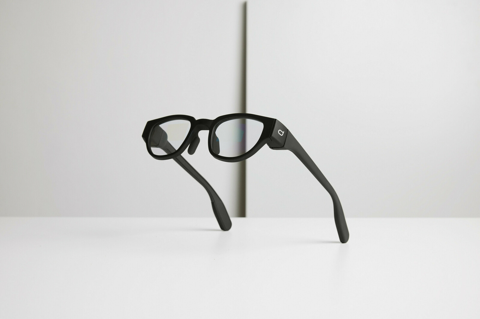
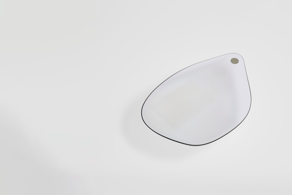
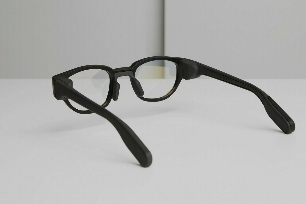
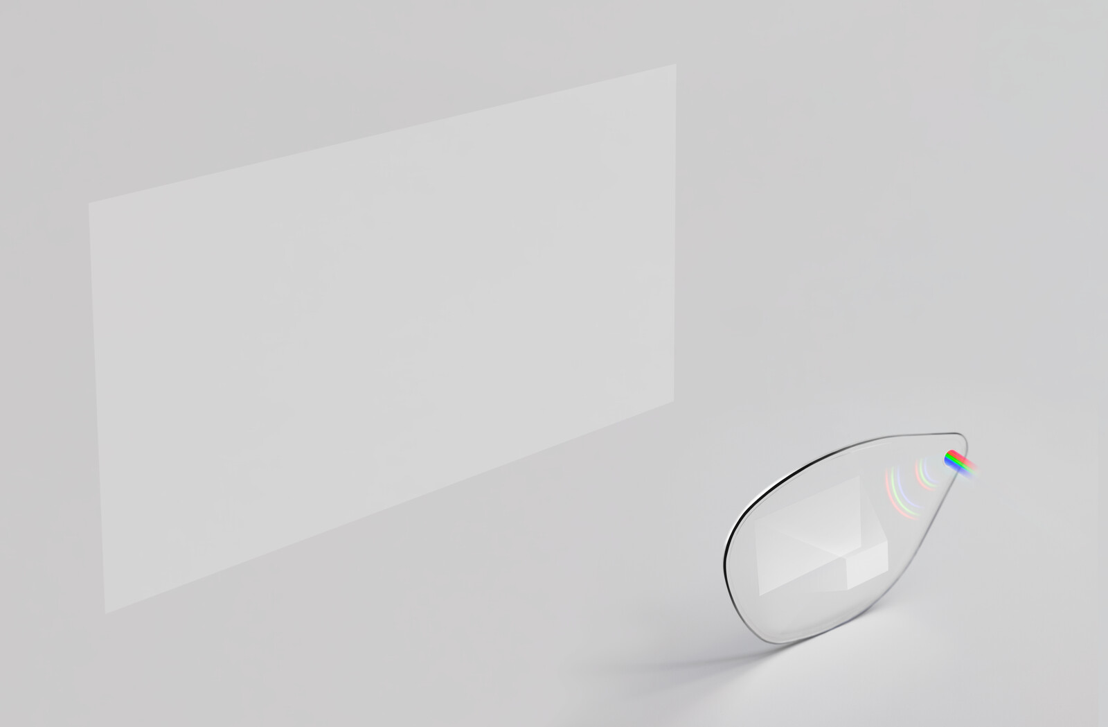
An example of an XR display in eyeglass form
Commercially available VR devices today rely primarily on video pass-through. Most VR devices are closed-style headsets or helmet-mounted devices (HMD) that block ambient light and allow the user to fully immerse themselves in the virtual world. In today’s AR and MR, optical see-through dominates. Depending on the use case, AR and MR devices can take any form, from an HMD to an eyeglass-form near-eye or mounted HUD. However, these technological divisions should be approached with care as the boundaries separating them are evanescent and constantly shifting. Video pass-through has been experimented with in AR and MR, and the level of immersion can be increased by utilizing optical see-through. Video can be combined with see-through to create video see-through. As XR is in a nascent form, the opportunities for exploration are immense.
Dispelix see-through displays
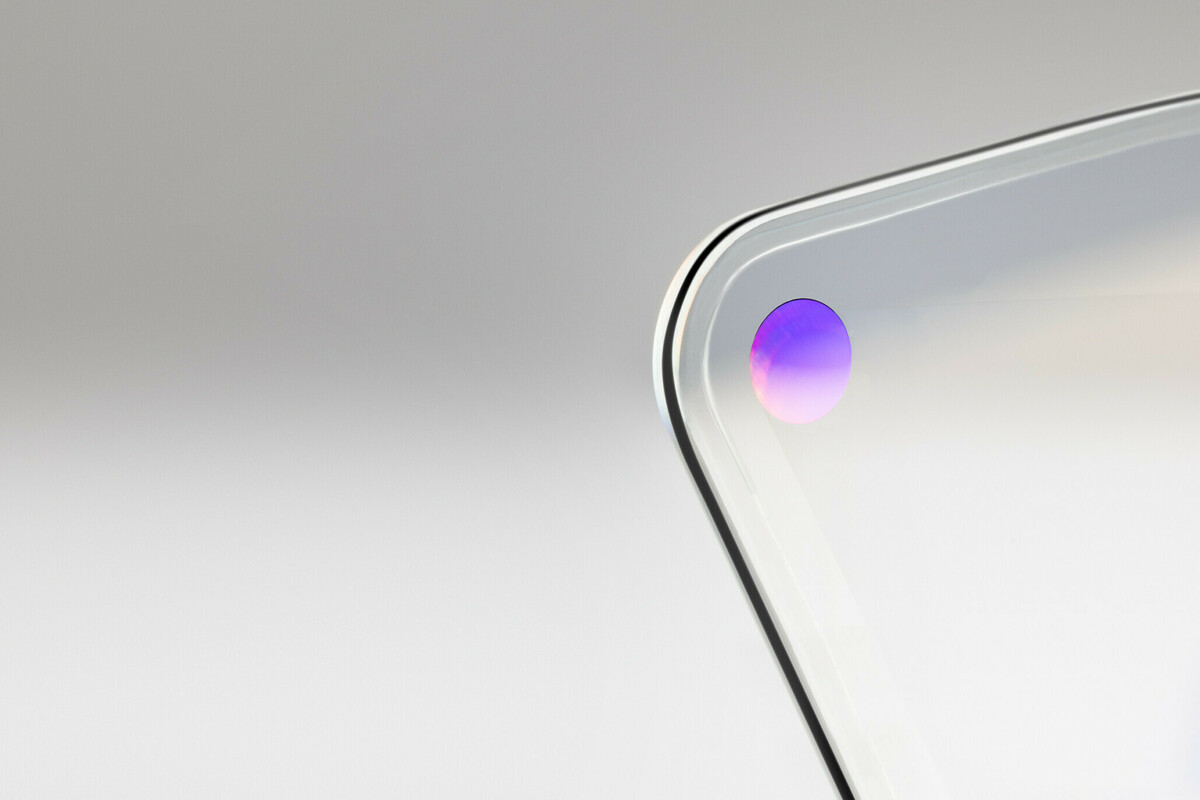
Dispelix develops and delivers light, high-performance see-through waveguide combiners that are used as transparent displays in a wide variety of XR devices. Our full-color waveguide displays can take any form between a minimalistic, eyeglass-lens shape and a large head-up display solidly mounted in vehicles or aircraft.
Dispelix engineers XR waveguide combiners from the design to a finalized component ready to be delivered for a customer. We offer thin, full-color waveguide combiners designed into eyeglass-form for near-eye display applications. We also design and develop custom displays for strategic partners and customers. Dispelix has adopted a fabless business model that allows us to leverage the volume manufacturing capacity of the world’s leading display technology powerhouses.
Dispelix technology is well-suited for versatile AR and MR applications. For simplicity, from hereon we refer to Dispelix waveguide combiners as XR waveguide combiners fully acknowledging their best performance shows up in the MR and AR end of the XR spectrum.
Viable see-through display technologies
The following sections will introduce specific terms commonly used in optics and photonics, and in XR literature in particular. The first instance of each term is in bold – unless explained directly in the text the definition can be found in the glossary at the end of this paper.
In optical see-through, the image is overlaid onto the real world by an optical combiner. The optical combiner collects the image from the light engine exit pupil, expands the exit pupil to the desired dimensions and, with the assistance of the human visual system, projects the image into the user’s field of view. Optical combiner architectures are many and multifold, but all aim to deliver reasonable image quality while maintaining a balance between wearability and performance-related parameters like field of view and brightness. Combiner architectures range from traditional approaches utilizing free-space optics, half-reflecting mirrors, and various birdbath architectures, to more advanced waveguide combiners.
The term waveguide refers to the ability of glass and polymer-based materials to guide lightwaves. They owe this unique capability to the refractive index, a physical parameter describing material optical density. The optical density of glass and polymer-based materials is relatively high compared to the optical density of air, the medium in which they exist. Because of this intrinsic material feature, lightwaves are confined to the glass or plastic and carried through the material by total internal reflection, a phenomenon in which lightwaves bounce back to the material whenever they encounter a material-air interface at an appropriate angle. A waveguide combiner is an optical combiner that relies on this waveguiding property of the display material.
Waveguide combiners are forecast to dominate the future AR and MR display markets as they can combine a compact, practical form factor with high image quality and performance at a price point that is affordable to mainstream consumers. Waveguide combiners can be divided into three broad categories based on the underlying optical combiner phenomenon they rely on. These categories are described in the next section.
Reflective optical elements
Reflective optical elements (ROEs) utilize the reflective properties of micron-scaled facets fabricated into display material. The facets act as mirrors that reflect the light in the desired direction, hence their alternative name, cascaded micro-combiners for ROEs. The light coupling, image expansion, and projection to the eyebox are performed by facets with optimized angles for each operation. Exit pupil-expansion by ROEs is a brightness-efficient and accurate way of relaying images in XR displays.
Diffractive optical elements
Diffractive optical elements (DOEs) have the unique ability to shape, split, and direct light intensity in an accurate, pre-determined way. They are used in a broad range of applications as a simpler solution to replace bulky, aberration-heavy traditional optics. Diffraction occurs when a lightwave encounters sub-wavelength obstacles or apertures (or a single obstacle or aperture) in its path of propagation. Apertures act as secondary sources of coherent lightwaves that interact with each other, resulting in regular, albeit sometimes complex, intensity variations that depend on the phase of lightwaves at each equivalent spatial point. Intensity variations formed through diffraction are called interference patterns. DOEs are extremely versatile elements in both design and manufacturing. They range from simple single-aperture devices and binary gratings to complex three-dimensional periodic structures. In the context of XR, DOEs are employed in the light coupling to the waveguide, in pupil expansion and replication, and in out-coupling to the eyebox. In binocular cases, they can project a stereo image at a comfortable distance for the user. Depth of view can be incorporated through various computer-generated holography or light-field projecting schemes.
Surface relief grating (SRG) is a special type of diffractive optical element widely used in XR waveguide combiners. SRGs are periodic nanostructures with sub-wavelength dimensions, deflecting incoming lightwaves into set angles called diffraction orders. Diffraction characteristics are defined by grating shape and dimensions, material refractive indices, and by the properties of the incoming wavefront, i.e., its wavelength, shape, and angle. SRGs can operate either in reflective or transmissive mode, or in both simultaneously.
Operating principle of an SRG waveguide combiner is presented in the figure above. The in-coupler collects and diffracts the incoming lightwave predominantly to the first diffraction order. The lightwaves are carried by total internal reflection in the waveguide. The SRG at the out-coupler directs lightwaves to the eyebox, from where the user’s visual system projects the virtual image into the user’s field of view. The virtual image is formed at optical infinity.
Holographic optical elements
At the heart of a holographic optical element (HOE) is a hologram, a two-dimensional device able to record the interference pattern of two intersecting coherent light fields. In holography, these fields are called the reference and object fields. When illuminated by the reference field, the hologram diffracts the field, regenerating the original object field. Unlike light-sensitive films used in traditional photography, HOEs utilize both the amplitude and phase information of the light field1. The unique ability to construct three-dimensional images of an object makes HOE an attractive option for XR displays. HOE is a special case of a diffractive optical element (DOE).
Choosing the best technology for your optical see-through implementation is the sum of many things. The key drivers in both consumer and enterprise solutions are undoubtedly image quality and performance factors like display brightness, contrast and resolution, color gamut, field of view, and lack of artifacts. The deeper into the consumer sphere we go, the more important considerations like product appeal and wearability become. These include characteristics like display transparency, weight, form factor, and lack of glow while the device is turned on.
Exponentially growing market demand
Today the XR market is driven by rapidly evolving use cases in the enterprise sector. XR adoption provides tremendous productivity increases and safety advances in the fields of education and remote training, medicine and healthcare, maintenance and repair, warehousing and logistics, navigation, aerospace, and defense, just to mention a few. Businesses on the leading edge are embracing XR technology with enthusiasm. Today, enterprise demand pushes the boundaries of XR with an emphasis on performance over form factor. Breakthroughs in enterprise XR expedite the emergence of innovative design solutions, combiner architectures, and material development. Consumer XR will undoubtedly benefit from the successes achieved in the enterprise field. A form factor approaching that of traditional eyeglasses alongside enterprise-driven performance paves the way for broader consumer acceptance of XR eyewear.
What does it take to make it into the mainstream?
To date, the size and shape of XR eyewear devices and their optical display modules has loosely followed the degree of immersion they provide – the more immersive the experience, the larger the device and its display optics. However, this logic will not hold true for much longer. Key players in the XR hardware industry have systematically invested in the development of technologies that enable the creation of XR eyewear that looks, wears, and feels like ordinary glasses. Dispelix is one of these players.
Glossary
Birdbath optical combiner utilizes beam splitters and spherical mirrors to expand and direct the image for the user.
Color gamut is the range of colors, or tones, that can be reproduced by the optical system. International Commission of Illumination (CIE) chromaticity maps are useful in presenting the complete color gamut and the subset of the color gamut achievable by the optical system.
Coherence describes how well lightwaves are synchronized with each other. Coherence has two aspects, spatial and temporal. Spatially coherent lightwaves move in unison and have strong correlation on the transverse plane, or across the beam profile. They are at the same phase across the transverse plane in reference to the direction of beam propagation. Temporally coherent lightwaves, on the other hand, share the same frequency along the direction of propagation; the correlation between time and distance traveled is strong.
Contrast in a display context refers to how well black and white can be distinguished when they coexist in an image. There are several ways to define and measure display contrast, with the most common methods being ANSI checkerboard contrast and FOFO (full-on/full-off) contrast.
Entrance pupil is the physical aperture, or the image of it, that defines the cone of light beam capable of entering the optical system, in this case the optical combiner in-coupler.
Eyebox is the volume between the eye and the XR display within which unconstrained, natural pupil movement is allowed, yet full field of view is visible to the user.
Eye relief refers to the distance between the outer surface of the cornea and the waveguide combiner at a distance where the user can still comfortably see the full field of view.
Exit pupil is the virtual aperture, or opening, through which the light beam can leave the optical system, in this case the light engine, without being blocked.
Exit pupil expansion (EPE) refers to the expansion function that occurs in EPE grating. Image leaving the light engine exit pupil is in millimeter-scale. One of the primary functions of an optical combiner is to stretch the light engine exit pupil to reasonable dimensions prior to light out-coupling to the eyebox. This function is called exit pupil expansion. Each optical combiner type has its own unique way of realizing the expansion.
Exit pupil replication refers to the replication, or cloning, of the light engine exit pupil to achieve EPE in optical combiners based on diffractive optical elements. Each time the lightwave hits the diffractive surface relief grating, part of the lightwave is diffracted and another part continues in the original direction until it hits the next SRG, where one part diffracts and another part continues, and so on. The DOE carrying out the EPE function has been designed to stretch the light engine exit pupil and direct the lightwaves to the out-coupler DOE.
Field of view (FOV) refers to the angular segment or range of the observable world visible to the human eye or any other device with a lens system (camera, microscope, binocular, telescope, etc.). FOV has both horizontal and vertical extends and can be defined for monocular or binocular vision.
Free-space optics refers to optical transmission in air or vacuum as opposed to transmission in an optical waveguide. Free-space optics utilize traditional optical elements like lenses, mirrors, aperture stops, and beam splitters to direct and control the light beam.
Frame-wrap refers to the angle waveguide combiners make from the frontal plane towards the temple sides.
Half-reflecting mirror transmits half of the light energy and reflects the other half. Half or partially reflecting mirrors are created using thin film stacks or thin metal films.
Light engine provides the image source for an optical display module. Light engines can be self-emissive (microLED, OLED) or reflective (LCoS, DLP). Light engine entails light sources and miniaturized projection optics. In the case of reflective light engines, illumination optics are also needed. Laser-based light engines utilize MEMS-mirrors to perform algorithm-driven laser beam scanning operation.
Liquid crystal display (LCD) utilizes light-modulating properties of liquid crystals. Electric current controls the polarization state of a liquid crystal which on the other hand defines whether polarized light transmits through the pixel. LCD is not self-emissive, it requires back-lighting. Thin film transistor (TFT) LCD is an active-matrix type LCD. In TFT LCD each pixel is controlled by one transistor. Transistors utilize thin film stacks with alternating insulating and semiconducting layers.
Luminous power, also called luminous flux, refers to the total quantity of light emitted by a source per unit time (unit lumens [lm]) perceived by the human eye.
Modulation transfer function (MTF) describes the ability of imaging optics to retain the detail of an input image. Images with a high MTF appear sharp while images with a low MTF are perceived as blurry or foggy to varying degrees. In optical terms, MTF translates into contrast as a function of spatial frequency2. Spatial frequency, or resolution, can be defined as line pairs per millimeter (lp/mm) or cycles per millimeter (cycles/mm). In short, MTF returns the system’s contrast at a fixed resolution.
Organic light-emitting diode (OLED) is a light-emitting diode (LED) made with organic emissive materials. Light emission is driven by electric current, like in the case of LEDs.
Pantoscopic tilt refers to a slight tilt downwards towards the facial side from the frontal plane.
Resolution describes the ability of human vision or an optical system to distinguish small features, or in case of displays, to present the image with certain accuracy. Depending on the setting, resolution can be measured as pixel density, units of length, line pairs per unit length, cycles per unit length, or as an angular resolution in units of pixels/cycles/line pairs per degree.
World-side leakage of a waveguide combiner describes how much of the luminous power is directed outside of the display, away from the eyebox. The preference is to have the smallest possible amount of luminous power leaking away from the user to ensure maximum brightness and to protect the privacy of XR content.